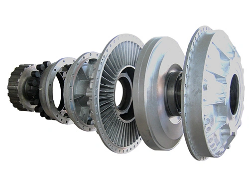

Fluid Couplings
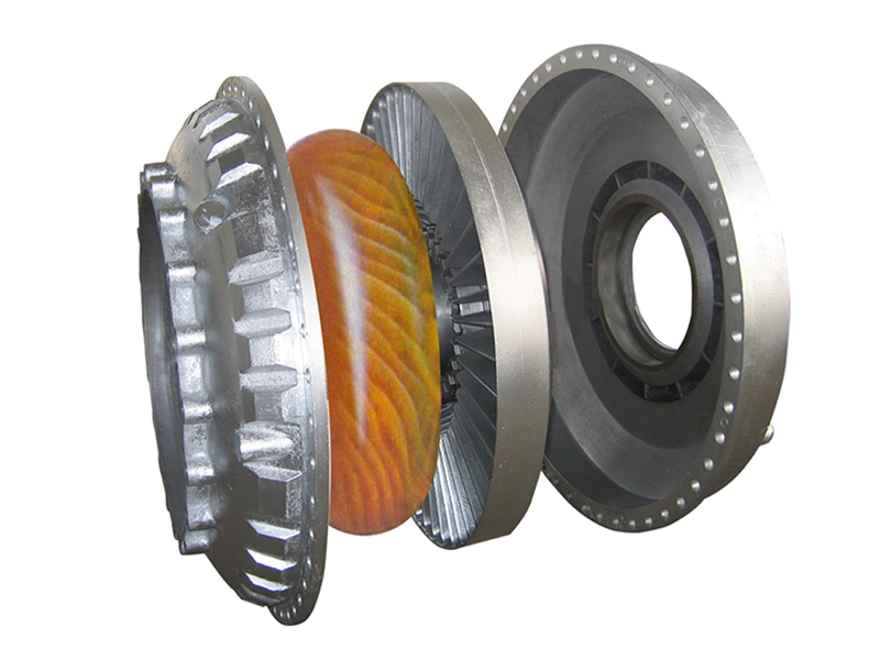
Fluid couplings are designed to provide smooth power transmission and controlled equipment startup in industrial drive systems. During startup, power is transferred gradually through the fluid and impeller, helping prevent shock loads that can damage motors, gearboxes, conveyors, crushers, and other rotating equipment.
By adjusting the internal oil level through the oil inlet or outlet, the coupling can precisely regulate startup performance under different working conditions. This allows the system to start in a more controlled manner while reducing sudden torque impact, vibration, and mechanical stress. It also provides reliable overload protection to help improve overall system operating life.
- Dual fusible plug protection Two fusible plugs are installed on the coupling to help protect the equipment from overheating caused by overload conditions originating from the driven machine or motor system.
- Optional proximity sensor system An optional proximity sensor can help prevent fluid leakage and allows the safety switch to be reset during frequent overload situations.
- Optional thermal trip protection An optional replaceable thermal trip breaker connected to a switch system can automatically stop fluid leakage under excessive temperature conditions.
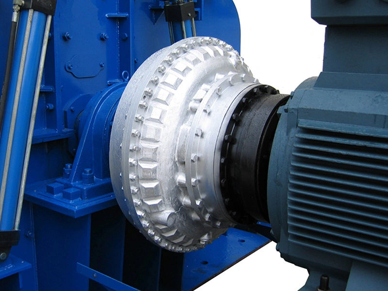
Suitable for a wide range of industrial drive systems, including belt conveyors, scraper conveyors, bucket elevators, ball mills, winches, crushers, excavators, mixers, straightening machines, cranes, and other heavy-duty industrial machinery
Under standard operating conditions and without special requirements, the fluid coupling model can be selected according to the motor speed (input speed of the coupling) and required transmission power based on the model selection table. The coupling uses oil as the transmission medium.
| Model | 600r/m | 7200r/m | 9700r/m | 14500r/m | 17500r/m |
| Transmitted Power (HP) | |||||
| | 2.5~5 | 6~12 | 20~40 | 35~70 | |
| | 3~7 | 8~16 | 25~50 | 45~90 | |
| | 5~10 | 12~25 | 30~65 | 55~120 | |
| | 6~12 | 13~26 | 40~80 | 70~140 | |
| | 9~18 | 20~40 | 60~120 | 110~220 | |
| | 15~30 | 35~65 | 90~200 | 150~325 | |
| | 16~32 | 36~72 | 100~205 | 170~340 | |
| | 25~50 | 60~120 | 180~360 | 300~600 | |
| | 35~65 | 80~150 | 240~480 | 350~700 | |
| | 50~100 | 120~240 | 320~640 | 450~900 | |
| | 48~100 | 90~190 | 220~440 | 500~1000 | 800~1000 |
| | 90~190 | 180~360 | 410~825 | 1020~1450 | |
| | 190~400 | 360~800 | 825~1450 | ||
| | 400~825 | 780~1600 | |||
| | 600~1250 | 1200~2450 | |||
| | 800~1600 | 1450~3200 | |||
| | 1600~3450 | ||||
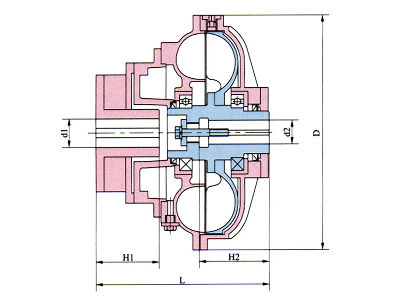
- When H1 or H2 exceeds the listed maximum values (H1MAX / H2MAX), the corresponding L dimension can be increased accordingly.
- The set screw inside the shaft bore shown in the drawing is an optional component.
| Model | Lmin | D | Input Bore | Output Bore | Oil Filling (gal) | Weight w/o Oil (lb) | Max. Speed (r/min) | Overload Ratio | |||
| D1max | H1max | D2max | H2max | Max. | Min. | ||||||
| | 12.20 | Ø 16.54 | Ø 2.17 | 4.33 | Ø 2.17 | 4.33 | 1.87 | 0.94 | 108 | 1450 | 2~2.5 |
| | 12.60 | Ø 17.72 | Ø 2.36 | 5.51 | Ø 2.36 | 5.51 | 2.22 | 1.11 | 128 | 1450 | 2~2.5 |
| | 14.02 | Ø 18.90 | Ø 2.36 | 5.51 | Ø 2.36 | 5.91 | 2.46 | 1.23 | 143 | 1450 | 2~2.5 |
| | 14.49 | Ø 19.49 | Ø 2.36 | 5.51 | Ø 2.36 | 6.30 | 3.17 | 1.58 | 154 | 1450 | 2~2.5 |
| | 15.63 | Ø 20.87 | Ø 2.95 | 5.51 | Ø 2.76 | 5.51 | 3.43 | 1.72 | 154 | 1450 | 2~2.5 |
| | 16.18 | Ø 23.23 | Ø 3.35 | 6.69 | Ø 3.35 | 5.71 | 5.07 | 2.53 | 231 | 1450 | 2~2.5 |
| | 16.77 | Ø 23.23 | Ø 3.35 | 6.69 | Ø 3.35 | 7.28 | 5.02 | 2.51 | 262 | 1450 | 2~2.5 |
| | 17.68 | Ø 24.96 | Ø 3.94 | 6.69 | Ø 4.33 | 6.69 | 7.92 | 3.96 | 288 | 1450 | 2~2.5 |
| | 18.66 | Ø 27.36 | Ø 3.54 | 6.69 | Ø 3.94 | 7.09 | 9.50 | 4.75 | 352 | 1450 | 2~2.5 |
| | 21.10 | Ø 29.13 | Ø 4.92 | 8.86 | Ø 5.12 | 7.87 | 12.14 | 6.07 | 482 | 1450 | 2~2.5 |
| | 24.37 | Ø 33.15 | Ø 5.51 | 9.84 | Ø 5.91 | 9.84 | 17.95 | 8.98 | 730 | 1450 | 2~2.5 |
| | 27.72 | Ø 38.50 | Ø 6.30 | 11.02 | Ø 6.30 | 10.43 | 29.30 | 14.65 | 1034 | 1450 | 2~2.5 |
| | 29.29 | Ø 44.29 | Ø 6.30 | 9.84 | Ø 6.30 | 11.02 | 38.02 | 19.01 | 1320 | 970 | 2~2.5 |
| | 33.46 | Ø 50.98 | Ø 7.09 | 11.81 | Ø 7.09 | 11.81 | 58.08 | 29.04 | 2002 | 720 | 2~2.5 |
| | 35.43 | Ø 55.35 | Ø 7.87 | 13.78 | Ø 7.87 | 13.78 | 71.28 | 35.64 | 2565 | 720 | 2~2.5 |
| | 37.52 | Ø 58.46 | Ø 7.87 | 13.78 | Ø 7.87 | 13.78 | 86.59 | 43.30 | 3168 | 720 | 2~2.5 |
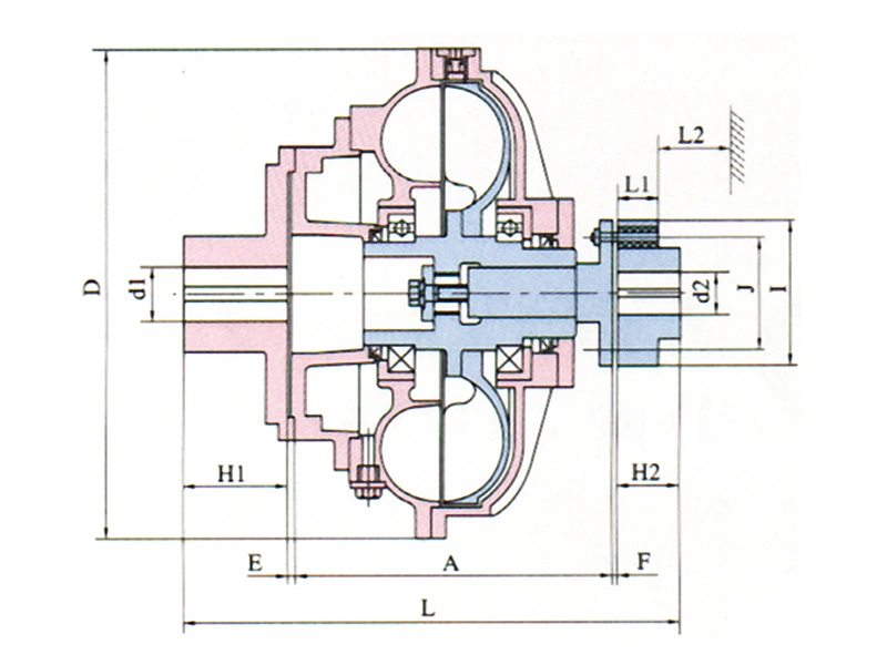
- The YOXE series combines the standard fluid coupling structure with an elastic coupling design, making alignment, installation, and maintenance more convenient during operation and equipment servicing.
| Model | D | E | A | F | L1 | L2min | I | J | d1max | D2max | Oil Filling (gal) | Weight w/o Oil (lb) | Max. Speed (r/min) | Overload Ratio | |
| Max. | Min. | ||||||||||||||
| | Ø 18.90 | 0.20 | 12.95 | 0.24 | 1.77 | 2.17 | Ø 7.48 | Ø 5.51 | Ø 2.36 | Ø 2.36 | 2.46 | 1.23 | 132 | 1450 | 2~2.5 |
| | Ø 19.49 | 0.20 | 12.95 | 0.24 | 1.77 | 2.17 | Ø 7.48 | Ø 5.51 | Ø 2.36 | Ø 2.36 | 3.17 | 1.58 | 176 | 1450 | 2~2.5 |
| | Ø 20.87 | 0.24 | 14.65 | 0.24 | 1.77 | 2.17 | Ø 8.66 | Ø 6.69 | Ø 2.76 | Ø 2.76 | 3.43 | 1.72 | 308 | 1450 | 2~2.5 |
| | Ø 23.23 | 0.20 | 14.45 | 0.24 | 2.17 | 2.76 | Ø 7.87 | Ø 7.68 | Ø 3.35 | Ø 3.35 | 5.07 | 2.53 | 297 | 1450 | 2~2.5 |
| | Ø 23.23 | 0.20 | 15.87 | 0.24 | 2.17 | 2.76 | Ø 10.24 | Ø 7.68 | Ø 3.35 | Ø 3.35 | 5.02 | 2.51 | 352 | 1450 | 2~2.5 |
| | Ø 24.96 | 0.20 | 16.06 | 0.31 | 2.17 | 3.15 | Ø 11.22 | Ø 8.46 | Ø 3.94 | Ø 3.94 | 7.92 | 3.96 | 528 | 1450 | 2~2.5 |
| | Ø 27.36 | 0.24 | 18.27 | 0.39 | 2.76 | 3.74 | Ø 12.99 | Ø 9.65 | Ø 4.33 | Ø 3.94 | 9.50 | 4.75 | 539 | 1450 | 2~2.5 |
| | Ø 29.13 | 0.20 | 18.66 | 0.24 | 2.76 | 3.74 | Ø 12.20 | Ø 9.06 | Ø 4.33 | Ø 3.54 | 12.14 | 6.07 | 572 | 1450 | 2~2.5 |
| | Ø 33.15 | 0.24 | 21.26 | 0.24 | 3.54 | 4.33 | Ø 14.17 | Ø 10.43 | Ø 4.72 | Ø 4.13 | 17.95 | 8.98 | 880 | 1450 | 2~2.5 |
| | Ø 38.50 | 0.28 | 24.29 | 0.47 | 3.54 | 4.33 | Ø 16.14 | Ø 12.20 | Ø 6.30 | Ø 6.30 | 29.30 | 14.65 | 1254 | 970 | 2~2.5 |
| | Ø 44.29 | 0.39 | 28.70 | 0.47 | 4.25 | 8.27 | Ø 22.44 | Ø 17.72 | Ø 6.30 | Ø 6.30 | 38.02 | 19.01 | 2618 | 720 | 2~2.5 |
| | Ø 50.98 | 0.31 | 32.68 | 0.47 | 5.12 | 8.27 | Ø 22.44 | Ø 17.72 | Ø 7.09 | Ø 9.45 | 58.08 | 29.04 | 3784 | 720 | 2~2.5 |
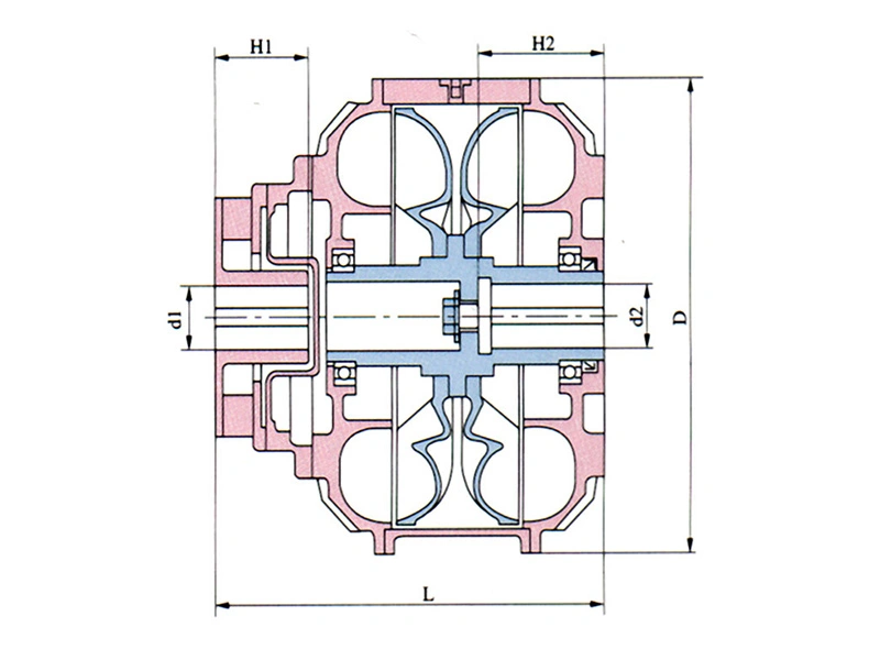
- The power transmission capacity of the YOXSQ series is twice that of the standard model with the same specification.
- The set screw inside the shaft bore shown in the drawing is an optional component.
| Model | Lmin | D | Input Bore | Output Bore | Oil Filling (gal) | Weight w/o Oil (lb) | Max. Speed (r/min) | Overload Ratio | |||
| D1max | H1max | D2max | H2max | Max. | Min. | ||||||
| | 18.50 | Ø18.90 | Ø2.36 | 5.51 | Ø2.36 | 5.91 | 4.75 | 2.38 | 264 | 1450 | 2~2.5 |
| | 19.69 | Ø20.87 | Ø2.95 | 5.51 | Ø2.76 | 5.91 | 6.60 | 3.30 | 308 | 1450 | 2~2.5 |
| | 22.05 | Ø23.23 | Ø3.35 | 6.69 | Ø3.35 | 6.69 | 9.50 | 4.75 | 396 | 1450 | 2~2.5 |
| | 24.02 | Ø25.59 | Ø3.54 | 6.69 | Ø3.94 | 7.09 | 13.20 | 6.60 | 572 | 1450 | 2~2.5 |
| | 25.20 | Ø27.36 | Ø3.54 | 6.69 | Ø3.94 | 7.09 | 18.48 | 9.24 | 660 | 1450 | 2~2.5 |
| | 27.95 | Ø29.13 | Ø4.72 | 8.86 | Ø5.12 | 7.87 | 23.76 | 11.88 | 880 | 1450 | 2~2.5 |
| | 31.50 | Ø33.15 | Ø5.51 | 9.84 | Ø5.51 | 8.27 | 33.79 | 16.90 | 1430 | 1450 | 2~2.5 |
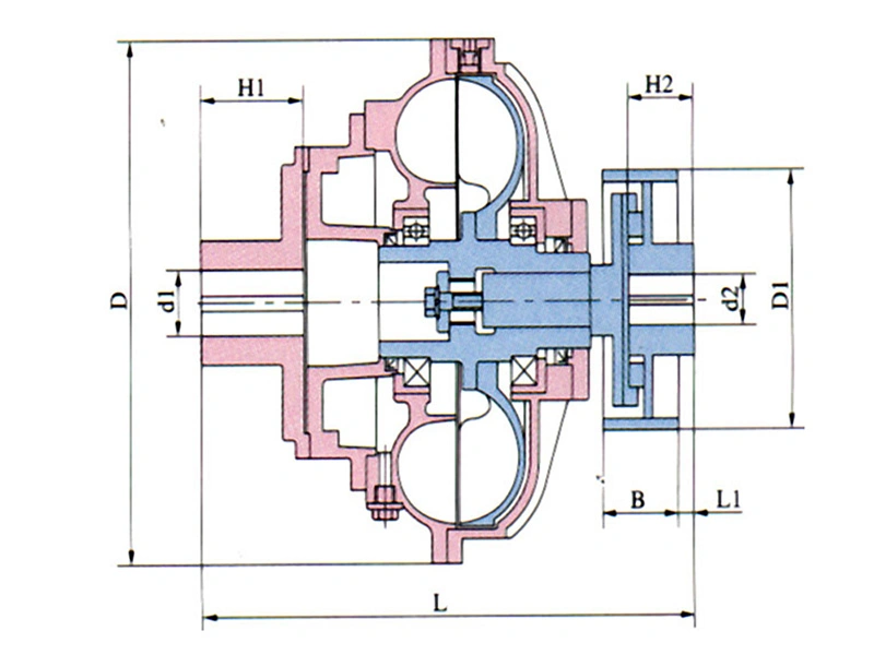
The YOXB series integrates a brake wheel structure into the fluid coupling system, making it suitable for industrial drive applications requiring controlled braking and power transmission functions.
Brake wheel dimensions can be customized according to application requirements.
| Model | Lmin | D | L1 | Input Bore | Output Bore | Brake Pulley | Oil Filling (gal) | Weight w/o Oil (lb) | Max. Speed (r/min) | Overload Ratio | ||||
| d1max | H1max | d2max | H2max | D1 | B | Max. | Min. | |||||||
| | 21.89 | Ø18.90 | 0.39 | Ø2.76 | 5.51 | Ø2.76 | 5.51 | Ø12.40 | 5.91 | 2.46 | 1.23 | 240 | 1450 | 2~2.5 |
| | 22.83 | Ø20.87 | 0.39 | Ø2.95 | 5.51 | Ø2.76 | 5.51 | Ø12.40 | 5.91 | 3.43 | 1.72 | 275 | 1450 | 2~2.5 |
| | 26.14 | Ø23.23 | 0.39 | Ø3.54 | 6.69 | Ø3.54 | 6.69 | Ø15.75 | 7.48 | 5.07 | 2.53 | 330 | 1450 | 2~2.5 |
| | 28.98 | Ø25.59 | 0.39 | Ø3.94 | 8.27 | Ø3.94 | 8.27 | Ø15.75 | 7.48 | 7.13 | 3.56 | 442 | 1450 | 2~2.5 |
| | 31.10 | Ø27.36 | 0.59 | Ø3.94 | 8.27 | Ø4.33 | 8.27 | Ø19.69 | 8.27 | 9.50 | 4.75 | 572 | 1450 | 2~2.5 |
| | 32.64 | Ø29.13 | 0.59 | Ø4.92 | 8.86 | Ø5.12 | 8.86 | Ø19.69 | 8.27 | 12.14 | 6.07 | 843 | 1450 | 2~2.5 |
| | 37.01 | Ø33.15 | 0.59 | Ø5.51 | 9.84 | Ø5.91 | 9.84 | Ø24.80 | 10.43 | 17.95 | 8.98 | 1052 | 1450 | 2~2.5 |
| | 40.94 | Ø38.50 | 0.79 | Ø5.91 | 9.84 | Ø5.91 | 9.84 | Ø24.80 | 10.43 | 29.30 | 14.65 | 1419 | 1450 | 2~2.5 |
| | 44.88 | Ø44.29 | 0.98 | Ø5.91 | 9.84 | Ø5.91 | 9.84 | Ø27.56 | 11.81 | 38.02 | 19.01 | 1863 | 720 | 2~2.5 |
| | 51.18 | Ø50.98 | 1.18 | Ø6.69 | 13.78 | Ø6.69 | 13.78 | Ø31.50 | 13.39 | 58.08 | 29.04 | 2314 | 720 | 2~2.5 |
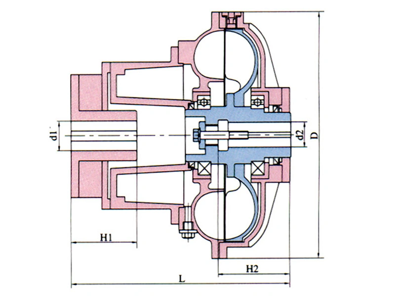
- The YOXY series features an extended rear auxiliary chamber, allowing a longer oil filling time from the auxiliary chamber to the working chamber. This design helps reduce starting torque and extend startup time, making it suitable for belt conveyors and other machinery requiring smoother startup performance. It also helps reduce impact on conveyor belts and extend belt service life.
- The set screw inside the shaft bore shown in the drawing is an optional component.
| Model | Lmin | D | Input Bore | Output Bore | Oil Filling (gal) | Weight w/o Oil (lb) | Max. Speed (r/min) | Overload Ratio | |||
| D1max | H1max | D2max | H2max | Max. | Min. | ||||||
| | 14.17 | Ø16.54 | Ø2.17 | 4.33 | Ø2.17 | 4.33 | 1.87 | 0.94 | 108 | 1450 | 1.2~2.35 |
| | 15.35 | Ø18.90 | Ø2.36 | 5.51 | Ø2.36 | 5.91 | 2.46 | 1.23 | 143 | 1450 | 1.2~2.35 |
| | 17.52 | Ø20.87 | Ø2.95 | 5.51 | Ø2.76 | 5.51 | 3.43 | 1.72 | 154 | 1450 | 1.2~2.35 |
| | 20.08 | Ø23.23 | Ø3.35 | 6.69 | Ø3.35 | 5.71 | 5.07 | 2.53 | 231 | 1450 | 1.2~2.35 |
| | 20.87 | Ø24.96 | Ø3.54 | 6.69 | Ø3.94 | 7.09 | 7.13 | 3.56 | 308 | 1450 | 1.2~2.35 |
| | 22.64 | Ø27.36 | Ø3.54 | 6.69 | Ø3.94 | 7.09 | 9.50 | 4.75 | 352 | 1450 | 1.2~2.35 |
| | 25.59 | Ø29.13 | Ø4.92 | 8.86 | Ø5.12 | 7.87 | 12.14 | 6.07 | 482 | 1450 | 1.2~2.35 |
| | 26.77 | Ø33.15 | Ø5.51 | 9.65 | Ø5.91 | 9.45 | 17.95 | 8.98 | 730 | 1450 | 1.2~2.35 |
| | 32.28 | Ø38.50 | Ø6.30 | 11.02 | Ø6.30 | 10.43 | 29.30 | 14.65 | 1034 | 1450 | 1.2~2.35 |
| | 33.27 | Ø44.29 | Ø6.30 | 8.27 | Ø6.30 | 11.02 | 38.02 | 19.01 | 1320 | 970 | 1.2~2.35 |
| | 37.80 | Ø50.98 | Ø7.09 | 8.66 | Ø7.09 | 11.81 | 58.08 | 29.04 | 2002 | 720 | 1.2~2.35 |
| | 42.32 | Ø58.46 | Ø7.87 | 9.45 | Ø7.87 | 13.78 | 86.59 | 43.30 | 3036 | 720 | 1.2~2.35 |